As always, the decision for switch or push-button depends on various factors.
The most important factor is the space on the handlebar.
Switches or buttons need space and must be accessible at the chosen location.
A toggle switch can be combined with the status LED/operating indicator on the handlebars on the universal indicator bracket without requiring additional space.
The operation indicator may not be necessary in quiet surroundings, but in the city and in busy traffic, the sound from the indicator box is no longer audible.
Die Taster hingegen sind intuitiver bedienbar. Es blinkt auf der Seite, auf der der Taster bedient wird. Added to this: The warning flashing can currently only be triggered with the buttons.
On the other hand, the toggle switch offers better feedback when switching and it can be felt almost blindly whether and in which direction it is flashing.
Operation with indicator switch (toggle switch)
When the toggle switch is mounted on an appropriately configured indicator box, flipping the toggle switch to the left triggers the turn signals to flash on the left side.
When the switch is returned to its original position, the flashing stops.
When the toggle switch is flipped to the right, the indicators flash on the right side.
If the switch is not returned to the initial position, the flashing stops automatically after 2 minutes.
Returning the toggle switch to the home position and switching it on again restarts the flashing.
Left and right refer to mounting the switch below the handlebar. Triggering the hazard warning lights is not possible with the toggle switch.
Operation with buttons
When the push-buttons are mounted on an appropriately configured indicator box, a short press on the left push-button triggers flashing of the turn signals on the left side.
If the left button is pressed again, the left turn signals stop flashing.
Pressing the button on the right side triggers the flashing of the turn signals on the right side.
If the right button is pressed again, the flashing stops.
Switching the flashing from e.g. left to right can be achieved by pressing the other button in each case.
If the indicators are not switched off manually, the flashing stops automatically after 2 minutes.
The hazard warning lights are triggered by switching on the other side.
Pressing and holding one button and pressing the other button starts the warning flashing.
It can be stopped again by pressing one of the buttons.
The warning flashing stops automatically after 15 minutes.
Configuration of the blinkerbox
The indicator box can be configured for different operating modes.
When ordering with switch or push-button unit, a correspondingly pre-configured indicator box is already shipped.
If the control unit is changed at a later date, it may be necessary to reconfigure the indicator box.
The push-buttons or a corresponding device and the connection to the power supply are necessary for configuration.
The configuration mode is set as follows: Keep one push-button permanently pressed and press the other push-button eight times in succession.
Then release both buttons. A short tone sequence sounds.
Now the indicator box is in configuration mode and the desired function can be set.
The following is an overview of which button presses determine which setting:
1nd button press: number of installed turn signals left button = 2 turn signals right button = 4 turn signals
2nd button press: button or switch operation left button = button right button = switch .
3rd button press: indicator sound on or off left button = indicator sound off right button = indicator sound on
This results in the following key combinations to select the software versions in configuration mode:
L indicates the left button, R the right button:
2 Turn signal switch with indicator tone
LRR
4 Turn signal switch with indicator tone
RRR
2 Turn signal switch with indicator tone
LLR
4 Turn signal switch with indicator tone
RLR
2 Turn signal switch without indicator tone
LRL
4 Turn signal switch without indicator tone
RRL
2 Turn signal switch without indicator tone
LLL
4 Turn signal switch without indicator tone
RLL
After entering the key combination, the configuration is completed and another short tone sequence sounds.
If no entry is made, the configuration mode is automatically exited after approx. 2 minutes.
The configuration is retained even after disconnection from the power supply.
Power supply of the blinkerbox
The electronics of the velorian e-bike blinker set are reverse polarity protected, so nothing will break if the plus and minus connections are reversed. It simply does not work. Likewise, the battery and motor of an e-bike are usually protected by multiple fuses. Because of the low power consumption of the velorian e-bike blinker set, the connection can be realized very easily at the headlight cable, as the following series of pictures shows. The connection is therefore just as simple as that of a spotlight.
Why cable? Because the battery can be used on the e-bike. This eliminates the need to check and recharge additional batteries before starting the ride. The velorian e-bike blinker set works with an input voltage of 6 - 55 Volt direct current, it is therefore not suitable for connection to a hub dynamo.
Some e-bike drive systems, such as Bosch, measure the consumption of the connected headlights and have defined a maximum value for this. This value must be determined beforehand with the specialist dealer, as the drive system can issue error messages if the load is too high, and correct function is then no longer guaranteed.
This maximum value should not be exceeded by the indicator and headlamp together when mounted on the headlamp connection cable.
The velorian e-bike blinker set has a rated power of 5 watts when all 4 turn signals are flashing.
With the turn signals shown in the example and available from us, it is even only 2.5 watts when all 4 turn signals flash.
On newer Bosch drive systems, power can also be tapped at the 3rd party port if Bosch ABS is not installed. The dealer must obtain an appropriate cable and enable the 3rd party port using the diagnostic tool.
Making the cableconnections
We recommend fitting the cables on the indicator box with the flat plug sleeves and the indicator and switch with flat plugs.
The advantage of crimp connectors is their relative vibration resistance and the ability to easily disconnect the connection at any time.
As the cable cross-section of the individual strands of 0.14 mm2 or 0.25 mm2 is considerably thinner than the cables with a cross-section of 0.75 mm2 usually used on bicycles, the smaller flat connector sleeves designed for this purpose should be used.
If crimp connectors are selected, the flat plug distributors are intended for connection to the power supply, with which the current-supplying cable can be divided.
These flat plug distributors are plugged onto flat plugs, so flat plugs must be crimped onto the cable ends on both sides.
The cable connections should be insulated with heat shrink tubing to prevent short circuits.
Alternatively, it is of course also possible to connect the cables with soldering hoses or the soldering iron.
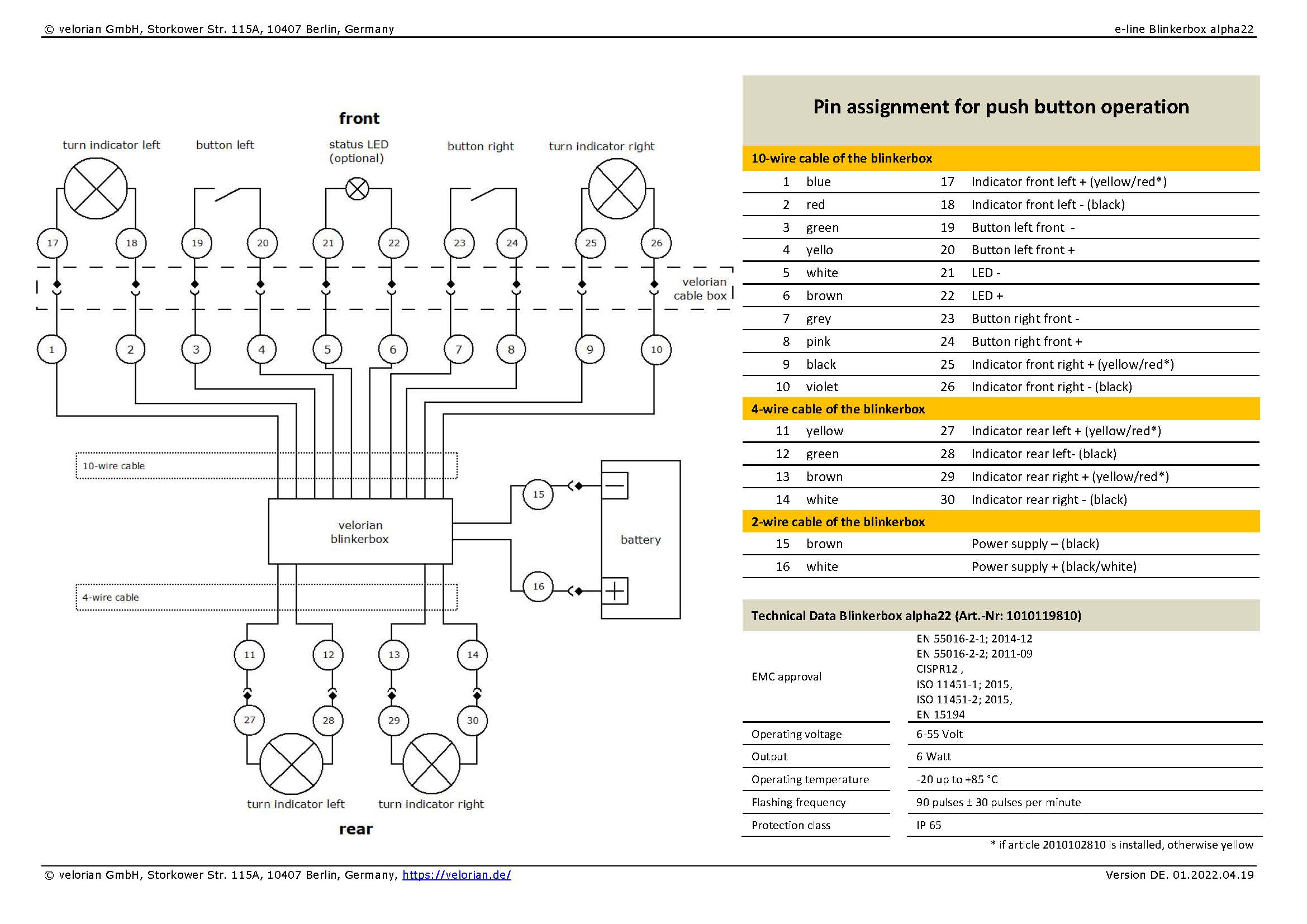
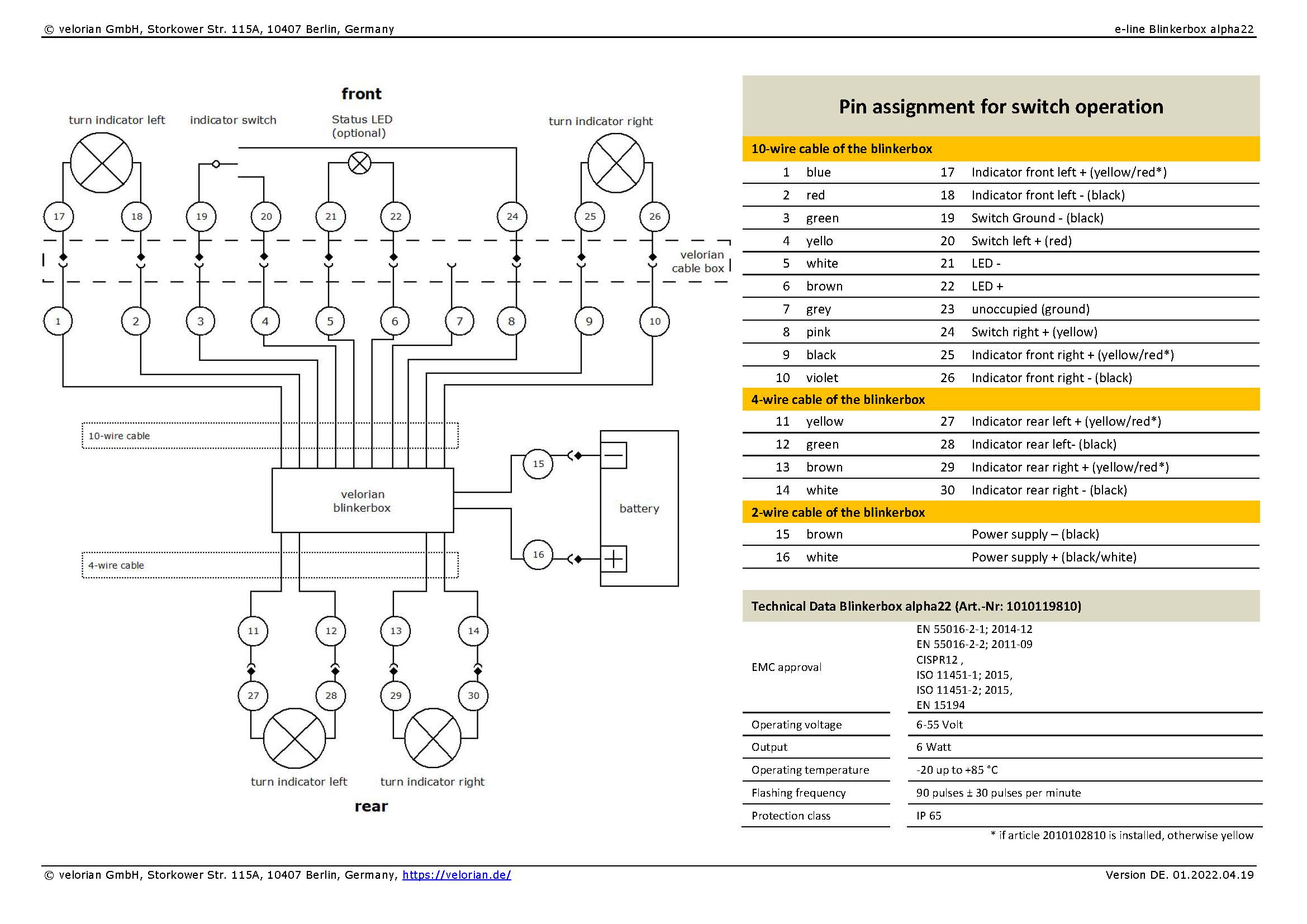
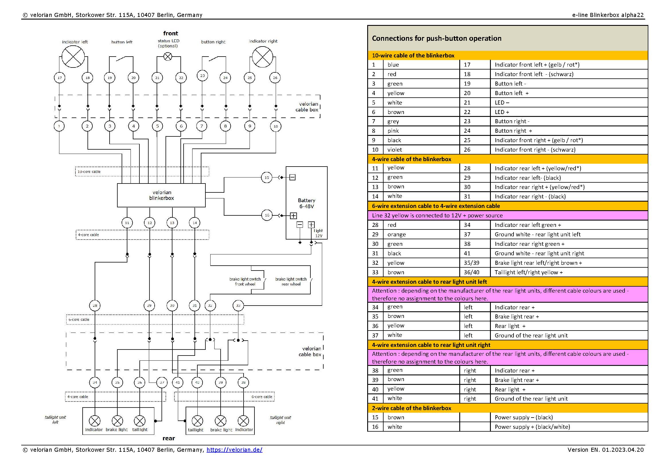
Wiring diagram/Connection assignment
Connection assignment for push-button operation Connection assignment for switch operation
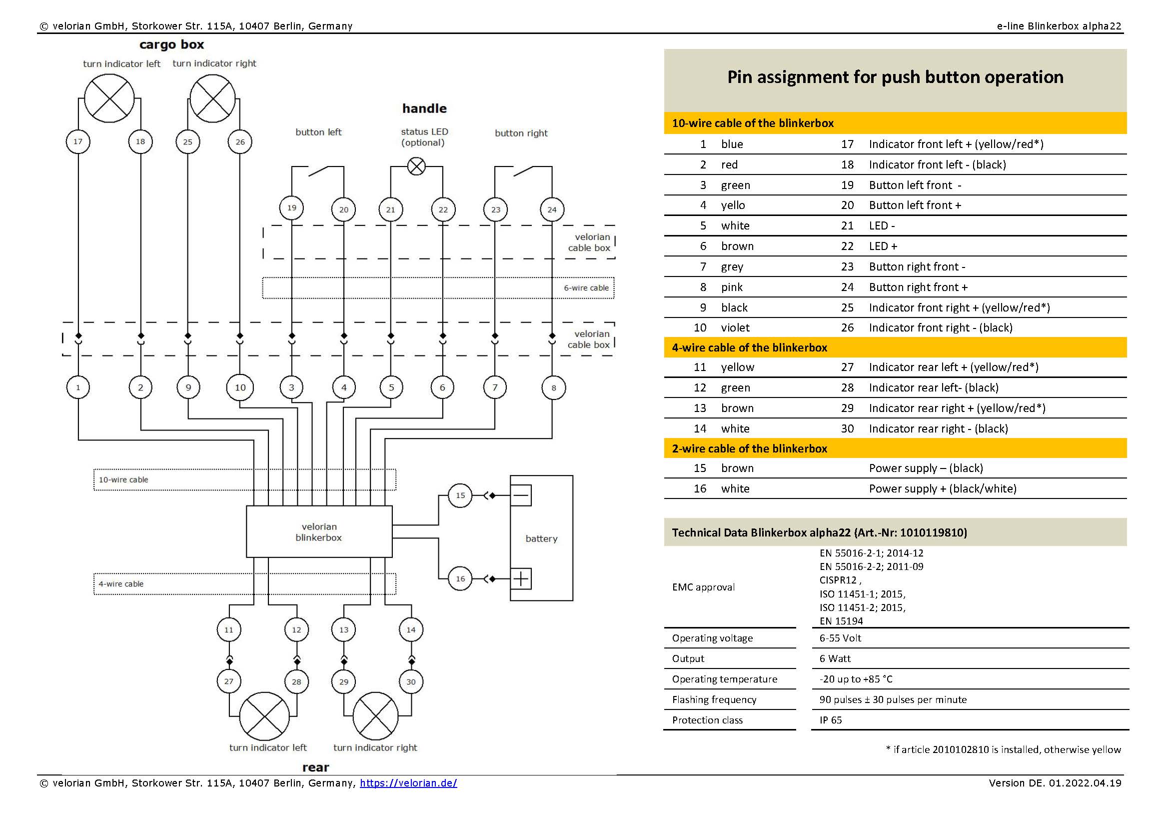
Wiring diagram/Connection assignment with special features on the cargo bike or tricycle
On a truck bike, recumbent or trike, it will not always be possible to mount the front turn signals on the handlebars or the rear turn signals close together.
This makes it necessary to extend the wiring harness.
The cable box can be used again for this if necessary.
Using the example of a multi-track cargo bike with a front cargo box, this results in the following layout, for example:
The 10-core cable from the blinkerbox is split into a 6-core cable with the lines to the button/switch and status LED and a 4-core cable to the front to the turn signals.
Instead of the 4-core cable, two 2-core cables can be used to reach the indicators on a wider cargo box.
The necessary cable material can be found in the shop.
Connection assignment for push-button operation Cargo
Wiring diagram/Connection assignment with special features for indicator combined with tail light and brake light
The use of combination turn signals or combination rear lights is also possible. A 12 volt lighting system is required! When connecting the combination rear lights, the ground connection of the turn signals (minus) from the indicator box must be used.
It does not matter which ground connection is used, as all ground connections in the indicator box are connected to one ground.
The tail light and brake light of the combination rear lights are connected to the plus cable of the lighting system.
The necessary cable material can be found in the shop.
Wiring diagram/Connection assignment with special features for indicator combined with tail light and brake light
General procedure for assembly
Safety instructions
The velorian e-bike blinkerset contains small parts that can be swallowed by small children.
There is a risk of injury when handling the cables and tools. We recommend assembly in a specialist workshop.
The electronics in the indicator box are reverse polarity protected.
This means that reversing the connection cables (mixing up plus and minus) on turn signals, switches or the power supply will not destroy the electronics or the connected components.
However, if the connections are interchanged, e.g. the power supply is connected to the cables for the turn signals, then the electronics can be destroyed when the current is switched on.
Likewise, poor insulation of the connecting cables can cause short circuits between them, which can destroy the electronics.
Blinkerbox
The first decision is where to mount the indicator box on the bicycle.
It should first be attached there provisionally so that the cable lengths can be determined.
The indicator box is splash-proof.
Nevertheless, the side with the two cables and the opening of the sound generator should be fixed in such a way that no water can collect on the sound generator.
This side should therefore preferably face downwards.
The housing with the control electronics, the turn signal box, is fastened with cable ties to a suitable place in the front area of the bicycle frame. The supplied cable ties are made of PU and UV-resistant and are therefore designed for permanent use in all weather conditions. It would also be possible to use coated stainless steel cable ties.
The lengths of the 3 connection cables have been chosen at 150 cm so that they are long enough for an optimal mounting position on an average bike, even on a high frame.
The cables are shortened to fit the respective bicycle frame during assembly and only then fitted with flat plugs and insulation.
If cables need to be split or extended, we have suitable cables for this in the shop.
The cables on the turn signal box are replaceable. If one cuts off too short during the assembly, this is annoying, but can be repaired by screwing on the housing and inserting a new longer cable.
During the test phase it became apparent that a status LED on the handlebars too often required a view of the handlebars from the road. That's why the indicator box has a sound generator that makes the flashing audible. The tone sounds almost like the flasher ticking in a car and is just loud enough to be heard while driving. The sound of the videos on this page is turned off. Turn it on to hear the flasher click.
If the ticking bothers you, you can switch it off via the indicator box configuration and mount an LED on the handlebars for this purpose.
Find the cable to the headlight. It's not always as loose on the wheel as it is here.
Now it takes courage to make that one cut.
The cable ends are fitted with flat plugs and insulated. The supplied distributors are plugged onto the compartment plugs.
Now the velorian e-bike blinker set is additionally connected to the headlight via the distributor.
This is what it can look like when it's finished.
Cable box
The next step is to attach the cable box to, for example, the handlebar stem or the head tube. To do this, use the longer cable ties supplied with the cable box.
Diese werden dazu durch die äußeren Laschen gezogen. The shorter cable ties can also be pulled through the inner tabs before mounting.
After connecting all the cables, they are used to secure the cables in the cable box and thus as strain relief.
1. Connect Cable
2. Sort into velorian Cable Box
3. Close velorian Cable Box
how to mount velorian Cable Box
Switch and indicator in front
From the indicator box, the 10-core cable should first be pulled to the handlebar. If the velorian cable box is used, the middle of the cable box is the end point. At this point, the cable can be shortened with a side cutter.
The cable, now shortened to length, can now be stripped, the individual strands stripped and fitted with flat connector sleeves. We recommend the use of appropriate tools for stripping and crimping.
Likewise, the front indicators and switches are now mounted, the connecting cables shortened to the correct length, the cable ends stripped and fitted with flat connectors.
Note: When shortening the cables, it is better to leave one or two centimetres too much cable than too little.
Be sure to turn the handlebars to one side and run the cable along the other side to determine the length.
Experience has shown that people tend to forget to turn in the handlebars and a cable is quickly too short.
In that case, nothing is lost, the cable can be reordered and replaced.
Video for mounting the indicators on the bowden cable brake lever
Video for mounting the turn signals with the universal turn signal holder
Connection of the powersupply and first function test
Once the front turn signals and switches are connected to the indicator box, a first function test can be carried out.
To do this, connect the 2-wire connection cable of the indicator box directly to the e-bike battery or another source such as the connection cable of the headlight.
Alternatively, the test can be carried out using a 12 volt power supply unit.
After switching on, the front turn signals will now still flash very quickly.
This is correct because the rear turn signals are still missing.
If a function test carried out at this point is successful, the connection to the power supply should first be disconnected again to avoid short circuits during further assembly!
Finally, the cable box can be closed.
Fitting the rear turn signals
First, the indicator bracket for the rear turn signals should be mounted on the wheel and the turn signals mounted on the bracket.
Now the 4-core cable can be routed from the indicator box to the mounting position of the rear turn signals, shortened to the correct length, the cable ends stripped and fitted with flat plug sleeves.
Similarly, the connecting cables of the turn signals are shortened to the correct length and the cable ends are stripped and fitted with flat connectors.
Once the rear turn signals are connected, the connection to the power supply can be re-established and a final function test can be carried out.
Video for mounting the indicators on the luggage rack
Mounting finish
At the end of assembly, the position of the switches and turn signals should be checked and all screw connections should be retightened.
The remains of the cables and the cable ties can be disposed of in the residual waste.
Warning function in case of failure of an indicator
If, for example, one of the rear turn signals fails (only with configuration for 4 turn signals):
the front indicator flashes twice as fast. If the front indicator fails, the rear indicator on the corresponding side flashes twice as fast.
the separate status LED (if installed) flashes twice as fast
the sound generator in the flasher unit (if active) ticks twice as fast
This behaviour is also triggered in the event of an assembly error with a short circuit on one of the turn signals.


 Find the cable to the headlight. It's not always as loose on the wheel as it is here.
 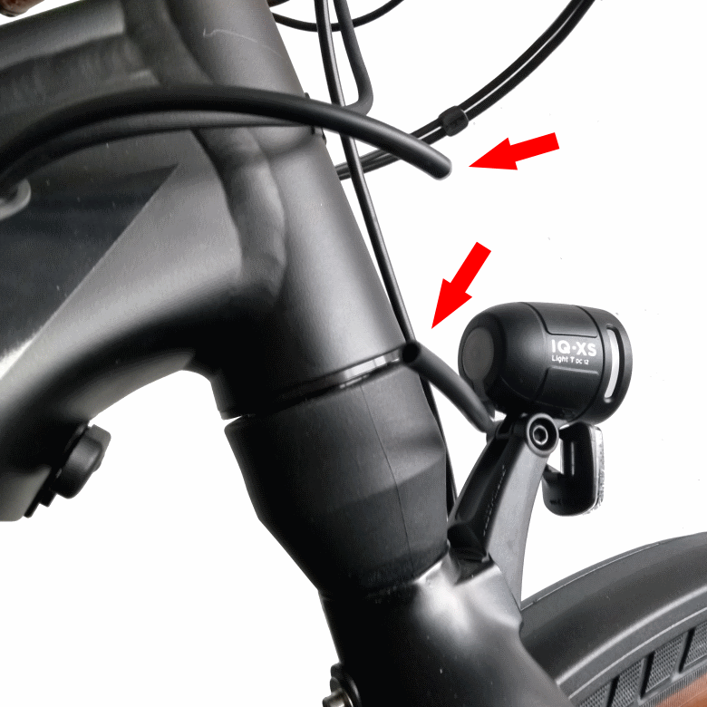 Now it takes courage to make that one cut.
 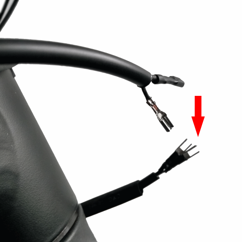 The cable ends are fitted with flat plugs and insulated. The supplied distributors are plugged onto the compartment plugs.
 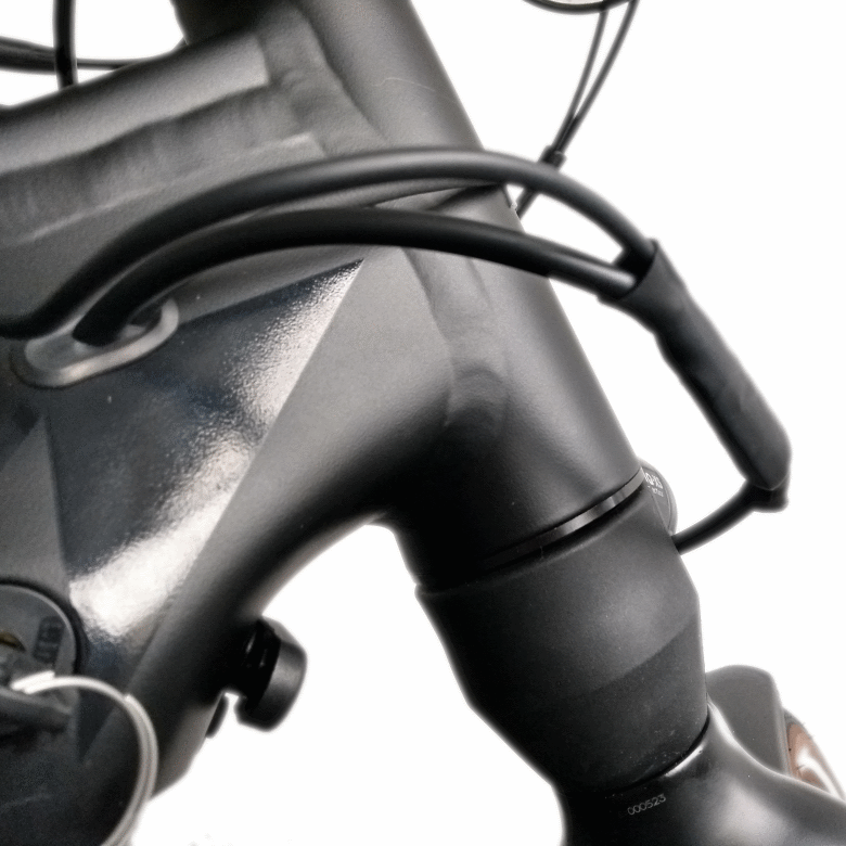 Now the velorian e-bike blinker set is additionally connected to the headlight via the distributor.
 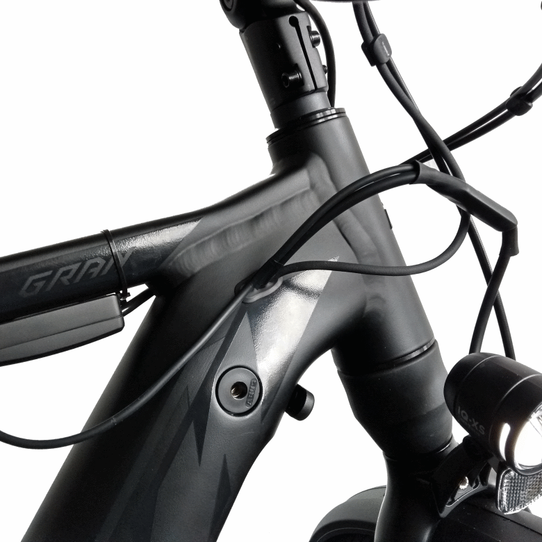 This is what it can look like when it's finished.
 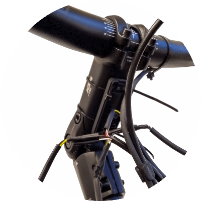 1. Connect Cable
 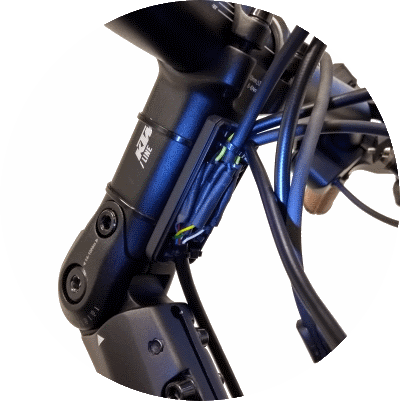 2. Sort into velorian Cable Box
 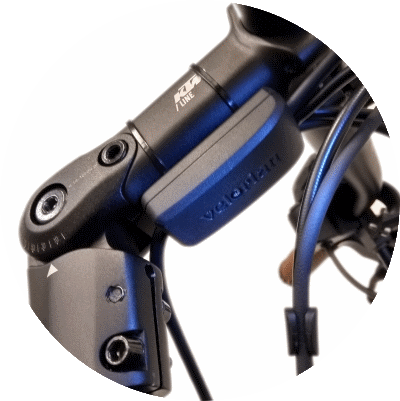 3. Close velorian Cable Box